Flange End Ball Valves
Two-piece full bore ball valve features a spherical disc to open and close the flow of the fluid. The valve is made to meet industry standard for pipeline shut-off application purposes. Valves are mechanical devices that control the flow and ensure the pressure within a pipeline system or process.
Valves are solely manually operated without any attached gear or power assist device. It shall be fitted with lever type handle which is blue or red in colour. The valve design guarantees a tight and leak-free sealing even after years of operation. They are essential components in a piping system installation that convey liquids, gasses, slurries etc.
Valves are solely manually operated without any attached gear or power assist device. It shall be fitted with lever type handle which is blue or red in colour. The valve design guarantees a tight and leak-free sealing even after years of operation. They are essential components in a piping system installation that convey liquids, gasses, slurries etc.
Size |
|
Material |
|
Working Pressure |
|
Connection Type |
|
Product Specifications
For more information on the individual product specifications, please click on the links below:

What are flange end ball valves
1. What is a flanged ball valve?
The inside of the ball has a hole through which the flow passes freely when it is fully aligned with both valve’s end. When the inside hole is completely perpendicular to the end of the device, the valve is sealed perfectly. If the hole is in any other position or not perpendicular to the valve ends, the flow will partly or totally be interrupted.
The inside of the ball has a hole through which the flow passes freely when it is fully aligned with both valve’s end. When the inside hole is completely perpendicular to the end of the device, the valve is sealed perfectly. If the hole is in any other position or not perpendicular to the valve ends, the flow will partly or totally be interrupted.
|
Ball valve can be categorized according to multiple criteria below:
|
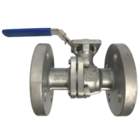
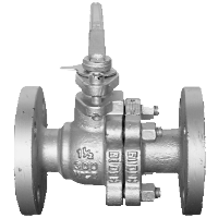
PN10/16 SS316 Flange End Ball Valve
|
2. What is fire safe ball vale design?
The fire safe valve design is to defeat or maintain a strategic distance from ignitable fluid, liquid or gas to pass through at any rate given any occasion in the midst of that time period not in segregating aggregates. There is danger that comes within installations in the oil and gas, chemical and petrochemical industries, whereby valves with fire safe design is reliable in case of a fire.
Standard features and advantages of fire safer valves:
TÜV SÜD will conduct a fire safety test to ensure that the valve demonstrates minimal leakage and can be operated in case of any fire environment. The valves are placed under 75% of the maximum working pressure in water application and it would be able to withstand fire temperatures between 750°C to 1000°C with a timeframe of 30 minutes.
Next, the examiner will cool down the valve for 10 minutes to below 100°C. Throughout the testing process, leakages from the valve seat to the atmosphere are measured with strict limits and they must be able to go through at least one full open and close cycle after the testing process is completed.
There is different level of fire safety that the valves can insure.
The fire safe valve design is to defeat or maintain a strategic distance from ignitable fluid, liquid or gas to pass through at any rate given any occasion in the midst of that time period not in segregating aggregates. There is danger that comes within installations in the oil and gas, chemical and petrochemical industries, whereby valves with fire safe design is reliable in case of a fire.
Standard features and advantages of fire safer valves:
- Blowout proof system
- Anti-static device
- Fire safe seat design
- Rubber O-ring stem sealing to maintain stem alignment, reduce packing side-loading and wear enhances stem seal performance.
- Double body sealing to ensure positive body joint sealing against pipeline stresses.
- Multiple stem sealing.
- Fire safe design conforms to API 607 standard.
TÜV SÜD will conduct a fire safety test to ensure that the valve demonstrates minimal leakage and can be operated in case of any fire environment. The valves are placed under 75% of the maximum working pressure in water application and it would be able to withstand fire temperatures between 750°C to 1000°C with a timeframe of 30 minutes.
Next, the examiner will cool down the valve for 10 minutes to below 100°C. Throughout the testing process, leakages from the valve seat to the atmosphere are measured with strict limits and they must be able to go through at least one full open and close cycle after the testing process is completed.
There is different level of fire safety that the valves can insure.
- Fire safe by design – designed to be fire safe and it hasn’t been tested.
- Fire safe tested – valve may have been tested and it hasn’t been approved by a governing third party.
- Fire safe certified and approved - valve has been certified and approved via test from governing third party in accordance to standards such as API 607, API 6 FA and ISO 10497.
3. How does a floating ball valve work?

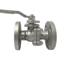
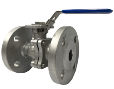
ANSI 150# SS316 Flange End Ball Valve
|
Ball valve is made in a floating valve design. The ball is suspended in the flowing fluid and keeping in position by the compression of two elastomeric seats against it. The shaft connected at the top of the ball allows a quarter 90-degree turn movement to switch the valve from an opening to closing position easily.
A load is applied to the ball which gets pressed against its seats when the shaft is moving. The floating design is lightweight and economic. It can suit bore size up to 10” and if the bore size is above 10”, the seats of the valve would not be able to withstand a heavier ball and the valve would not operate efficiently and safely. |
When the valve works under medium pressure, the floating ball will move against the downstream seat. The seal of the valve belongs to the single-sided seal. The floating valve has upper stem so that the ball can have a light displacement. When the valve is closed, the floating ball is pressed against the sealing surface under the action of pressure to realize sealing. The valve is suitable for medium and low pressure and valve size which has a small diameter.
4. What is the difference between ANSI, JIS and ASME flange end ball valve?
Flange end connection ball valve is one of the common types that is to apply in hydraulics installation. There are three standard type of flange end connection ball valve. All three types of flange end connection have its end dimensions’ spec to follow and it is not interchangeable during installation.
The size reading in NPS is followed by a dimensionless number and it is the designation for nominal valve size. NPS is related to the reference nominal diameter DN, which is used in international standards. For NPS size more than 4”, it is generally related DN is DN = 25 (NPS). The relationship is typically as follows:
Flange end connection ball valve is one of the common types that is to apply in hydraulics installation. There are three standard type of flange end connection ball valve. All three types of flange end connection have its end dimensions’ spec to follow and it is not interchangeable during installation.
- American National Standards Institute, ANSI (ANSI 150#, ANSI 300#)
- Deutsches Institut für Normung, DIN (PN10, PN16, PN40)
- Japanese Industrial Standards, JIS (JIS5K, JIS10K, JIS16K)
The size reading in NPS is followed by a dimensionless number and it is the designation for nominal valve size. NPS is related to the reference nominal diameter DN, which is used in international standards. For NPS size more than 4”, it is generally related DN is DN = 25 (NPS). The relationship is typically as follows:
NPS Pipe Standard |
Nominal Diameter |
1/2" |
15 |
3/4" |
20 |
1" |
25 |
1 1/4" |
32 |
1 1/2" |
40 |
2" |
50 |
2 1/2" |
65 |
3" |
80 |
4" |
100 |
5" |
125 |
6" |
150 |
5. Are ball valves better?
|
Ball valve has the advantage as per below:
The working pressure and temperature rating of valve are determined by its shell materials and primarily sealing materials. Sealing materials may be high molecule or rubber material and the selection is limited due to different characteristics of the service fluid, working pressure, working temperature, velocity of fluid and operational frequency of valves. |
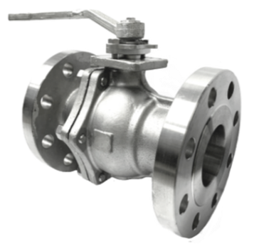
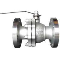
ANSI 300# SS316 Flange End Ball Valve
|
6. How do you assemble a ball valve?
6.1 Liquids with high velocity
When ball valve operates frequently on liquids with high velocity, please check on the valve drawing or diagram to minimize the possibility of seat deformation, especially when they are applied in highly pressurized and high-temperature pipelines.
6.2 Valve selection
Valve selection is important with design specifications which meet the pressure and temperature condition required. Take note upon selecting the seats material as fluids containing abrasives might degrade the seats.
6.3 Valve mounting
Check the pipe bore to confirm that there is no weld spatter, scale or rust particles remains inside before mounting the valve. To mount flange end ball valve, diagonally locate the flange bolts and it should be tightened evenly.
6.4 Valve opening degree
High maintenance and care should be attended to as ball valve is under the category of on/off valves. This is to ensure that the ball valve can open and close fully when they are installed in a pipeline system. Valve opening will result in seat erosion and may cause seat leakage. Pipelines that require ball valve for throttling service should be designed in consideration of the amount of seat leakage which may occur in its fully closed position. Please bear in mind that ball valves should be stored in a fully opened position.
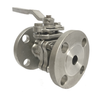
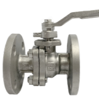
JIS 10K SS316 Flange End Ball Valve
|
6.5 High temperature and high pressure service
The pressure and temperature rating recommended by manufacturer is an appropriate guide to the maximum working pressure and temperature range that the valve can withstand. However, reference to valve distributor is needed for an assurance of suitability when ball valve is subjected to condition below:
|
6.6 Valve disassembly
The line fluid should be completely removed from the internal of the valve connection before they are dismantled from the pipeline for maintenance or repairing purposes. Fluid residues will always be present in the valve body and body cavity even though users have tried to discharge most of the fluids through the pipeline. Before valve disassembly, please be sure to completely discharge the pressure trapped in the body cavity.
The line fluid should be completely removed from the internal of the valve connection before they are dismantled from the pipeline for maintenance or repairing purposes. Fluid residues will always be present in the valve body and body cavity even though users have tried to discharge most of the fluids through the pipeline. Before valve disassembly, please be sure to completely discharge the pressure trapped in the body cavity.