Hydraulic SAE Flanges
SAE Flanges are designed to provide an alternative method of connecting a pipe, hose, tube or equipment. The leak free connection is suitable for high pressures, larger sizes and assembly in tight quarters. It has achieved worldwide standard acceptance.
It is made from normalized forging and the basic raw material is steel with carbon content lower than 0.30%. Alternatively, stainless steel SS316 or galvanized flange material is available. The complete set flange combine of flat face, oring face, oring groove, 4 washers and cap screws.
It is made from normalized forging and the basic raw material is steel with carbon content lower than 0.30%. Alternatively, stainless steel SS316 or galvanized flange material is available. The complete set flange combine of flat face, oring face, oring groove, 4 washers and cap screws.
Size |
|
Material |
|
Series |
|
Connection Type |
|
Configuration |
|
CATALOGUE :
What are Hydraulic SAE Flanges
1. What are hydraulic SAE flanges use for?
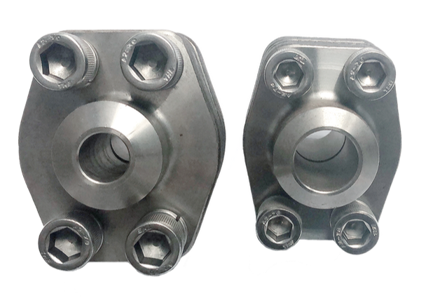
The 4-bolt hydraulic sae flange connection conforms to SAE J518 and ISO 6162 standards. The flange has through holes for the mounting bolts and it has UNC or metric thread. The mounting holes of flat face are tapped while oring face doesn’t include.
The 4-bolt hydraulic sae flange connection conforms to SAE J518 and ISO 6162 standards. The flange has through holes for the mounting bolts and it has UNC or metric thread. The mounting holes of flat face are tapped while oring face doesn’t include.
|
There are various bolt grades that are paired to install in equipment:
|
Manufactured with two kinds of material, Steel (ST52.3) and Stainless Steel AISI SS316L, these are the two commonly used materials for SAE Flanges in hydraulic systems.
Steel ST52.3 is a low alloy, high strength structural steel, known for its excellent weldability and machinability. It is often used in the construction of hydraulic components due to its excellent mechanical properties and durability. ST52.3 are preferred in hydraulic systems which require components capable of withstanding high pressure and mechanical stress.
Stainless Steel SS316L is a low carbon variation of SS316, a molybdenum-bearing austenitic stainless steel. SS316L offers excellent corrosion resistance, making it ideal for use in harsh environments and applications where corrosion resistance is a concern. Its material resistance to corrosion ensures longevity and reliability in challenging conditions.
Steel 52.3
AISI SS316L
Steel ST52.3 is a low alloy, high strength structural steel, known for its excellent weldability and machinability. It is often used in the construction of hydraulic components due to its excellent mechanical properties and durability. ST52.3 are preferred in hydraulic systems which require components capable of withstanding high pressure and mechanical stress.
Stainless Steel SS316L is a low carbon variation of SS316, a molybdenum-bearing austenitic stainless steel. SS316L offers excellent corrosion resistance, making it ideal for use in harsh environments and applications where corrosion resistance is a concern. Its material resistance to corrosion ensures longevity and reliability in challenging conditions.
Steel 52.3
- Made from low alloy, high tensile strength structural steel.
- Good weldability and machinability.
- Suitable for applications where high pressure and mechanical stress are required.
AISI SS316L
- Made from austenitic stainless steel SS316L.
- Excels in harsh environments or high moisture exposure.
- Ideal for applications where corrosion resistance is critical.
2. What type of O-rings are used for hydraulic flanges?
|
It is a static face seal which uses a high durometer O-ring for the flange sealing. Metal-to-metal contacts at the outer face of the flange will cause leakage. Therefore, the O-ring sealing is compressed between the flat face and O-ring face providing a reliable soft sealing. Flanges use an O-ring to seal a joint and contain pressurized fluid.
|
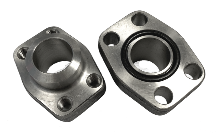
O-Ring Side SAE Flange
|
The seals of flanges are available in the following materials:
Description |
NBR 70/90 |
Viton 90 |
Equivalent |
BUNA-N |
FKM |
Temperature Range (°C) |
-34°C to 121°C |
-26°C to 205°C |
Recommended Application |
|
|
Non Recommended Application |
|
|
3. What is the difference between code 61 and 62 flanges?
The ISO 6162 standard defines two primary types of flanges for hydraulic systems: the standard pressure series (Code 61) and the high-pressure series (Code 62). While both codes serve similar purposes, these flanges have distinct differences in terms of design, pressure ratings and applications.
SAE Flange code 61 features a flat face with four bolt holes and an O-ring groove, designed for lower pressure applications. The flat face design allows for easy assembly and disassembly of components. Commonly used in applications which require moderate pressure ratings are sufficient, such as in agricultural machinery, construction equipment, and industrial hydraulics.
Same as SAE Flange code 62, features a flat face with four bolt holes and an O-ring groove, designed for higher pressure applications. Cone seat design provides a metal-to-metal seal, suitable for demanding hydraulic systems. SAE Flange code 62 is commonly found in applications requiring high pressure ratings, such as in aerospace, marine and heavy machinery industries.
SAE Flange is designed in two difference code design and it is code 61 and 62. The summary table as per below:
Description |
Code 61 |
Code 62 |
Series |
3000 |
6000 |
Size |
3/8” to 5” |
3/8” to 3” |
Working Pressure (bar) |
34 to 345 |
414 |
Difference Between Code 61 & Code 62
- Pressure Ratings
- Seal Type
- Construction and Dimensions
4. How are SAE flanges attached to pipe?
|
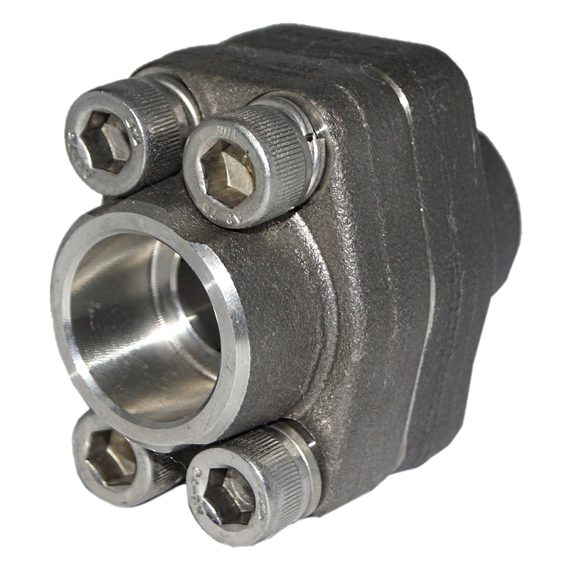
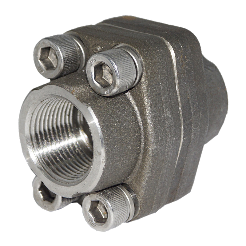
Hydraulic SAE flange provides a zero-clearance assembly that enables easy connection, disconnect and maintenance of tube to hose, tube to tube or manifold connection. Infinite positioning is a built-in feature to enable flange to put in different position angle. There are several types of connection: threaded end (NPT or BSPP) and welding end (socket weld or butt weld).
The connection of welding and threaded is able to maximize reliability. However, it is inevitable that connections must be removed to allow replacing or servicing on system components. To improve flanges productivity, flanges have advanced considerably before installation to improve performance, installation convenience but still remain overall function effectiveness and efficiency. |
5. What is the purpose of a SAE flange?
A simple SAE flange installation design provides several advantages:
A simple SAE flange installation design provides several advantages:
- Ability to connect pipe size up to 5 inch.
- Single seal point between pipe or system assembly.
- Much lower tightening torque required from the four bolts compared to other types of flange with equivalent size
- Ease of disassembly through use of split flange.
|
Step 1: Check components surface and ensure there are no damage or contamination.
Step 2: Align the flange connection before inserting the O-ring seal on the female flange groove. Place the washer with cap screws and bolt through the bolt holes. Step 3: Hand tighten cap screws to seat O-ring on flange groove. Step 4: Ensure the tighten process meets the torque value below: |
|
Flange Size |
Screw Thread |
Screw Torque (NM)* |
1/2" |
M8 |
32 |
3/4" |
M10 |
70 |
1" |
M10 |
70 |
1 1/4" |
M10 |
70 |
1 1/2" |
M12 |
130 |
2" |
M12 |
130 |
2 1/2" |
M12 |
130 |
3" |
M16 |
295 |
3 1/2" |
M16 |
295 |
4" |
M16 |
295 |
5" |
M16 |
295 |
Flange recommended Torque Value Table Series 3000 Code 61
Flange Size |
Screw Thread |
Screw Torque (NM)* |
1/2" |
M8 |
32 |
3/4" |
M10 |
70 |
1" |
M12 |
130 |
1 1/4" |
M12 |
130 |
1 1/2" |
M16 |
295 |
2" |
M20 |
550 |
2 1/2" |
M24 |
550 |
3" |
M30 |
650 |
Flange recommended Torque Value Table Series 6000 Code 62
To watch how to install sae flange video, please click this link.
FAQs
- What is a hydraulic SAE Flange?
- What are the main components of a hydraulic SAE Flange?
- What are hydraulic SAE Flanges used for?
- How do hydraulics SAE Flanges differ from other types of flanges?
- What are the different types of hydraulic SAE Flanges available?
- How do I select the right hydraulic SAE Flange for my application?
- What are the benefits of using hydraulic SAE Flanges?
- Can hydraulic SAE Flanges be reused?
- Are hydraulic SAE Flanges compatible with different hydraulic fluids?
- What maintenance is required for hydraulic SAE Flanges?
CATALOGUE :