Stauff Pipe Clamps
|
A Stauff clamp is a clamp that is used to grip tubes, pipes, and hoses along hydraulic systems. The actual purpose of the clamp itself is to keep the hydraulic system stable. They help reduce the impact and vibration that fluid flow creates. There are three different versions in the series of Stauff clamps. There is the standard series, heavy series and the twin series.
The clamp body is made of polypropylene (PP), polyamide (PA), aluminium (AL), and polypropylene with rubber insert (RI). Installation of Stauff Clamps are very easy as it only involves fixing the clamp itself onto a stable surface and wrapping the clamp along the pipe tightly in order to avoid any slack in the clamp. |
|
Series and Size |
|
Accessories Material |
|
Body Material and Temperature Range |
|
Clamp Accessories Availability |
|
CATALOGUE :
What are uses of Pipe Clamps
1. What is an advantage of using Stauff pipe clamps?
DIN 3015 Stauff Pipe Clamps boast a robust design tailored to secure pipes effectively within industrial settings. DIN 3015 clamps typically consist of two distinct halves, each equipped with elastomeric inserts, to ensure clamps a snug fit around the pipe, reducing vibrations and preventing movement.
Crafted from durable materials which would be polypropylene, polyamide, and aluminium, they exhibit excellent corrosion resistance, enhancing longevity even in harsh environments. Manufactured with a wide size range available, DIN 3015 are able to accommodate various configurations and sizes, based on pipe diameters and loads, catering to diverse application needs.
Notably, DIN 3015 Stauff Pipe Clamps adhere to stringent standards, guaranteeing consistency, quality, and compatibility with other DIN-compliant components. Their versatility extends across industries, finding utility in hydraulic systems, automotive setups, marine environments, and more. Moreover, installation is hassle-free, and ease of use renders DIN 3015 Pipe Clamps an economical, reliable choice for pipe or tube support and stabilization in industrial contexts.
DIN 3015 STAUFF Pipe Clamps offer several distinct advantages that set them apart as a preferred choice in industrial piping applications.
- Robust Support and Stability: Provide strong and reliable support to piping systems, ensure that pipes remain secure in place even under high pressure and dynamic conditions. Minimizes risk of pipe movement, reducing the potential for leaks, damage, and downtime.
- Vibration Damping: Helps minimize noise levels and mitigate the risk of wear and tear on pipes and adjacent equipment, which prolongs the lifespan of the piping systems and creates a safer and more comfortable working environment.
- Corrosion Resistance: Crafted using materials such as stainless steel, carbon steel, or aluminum, the clamps exhibit excellent resistance to corrosion. DIN 3015 STAUFF Pipe Clamps able to minimize the need for frequent maintenance and replacement, reducing overall operating costs.
- Adherence to Standards: DIN 3015 Pipe Clamps are manufactured in compliance with DIN standards, guaranteeing consistency, quality, and compatibility with other DIN-compliant components.
- Ease of Installation and Maintenance: Clamps are designed for easy installation and maintenance, the straight forward maintenance requirements further contribute to cost savings and operational efficiency. Its versatile design allows for seamless integration into various piping systems, ensuring compatibility and ease of use across different applications.
2. What is a pipe clamp used for?
A Stauff pipe clamp can refer as a tube clamp, a pipe clamp as well as hydraulic brackets. In essence they hold the pipes or tubes in place, keeping it stable and gripping it along its axis so that it stays still. The Stauff clamp that is available are made following the standards of the Deutsches Institut für Normung, better known as DIN. Specifically, the Stauff clamp follows the DIN 3015 standards.
Aluminium (AL), Polypropylene (PP), Polyamide (PA)
|
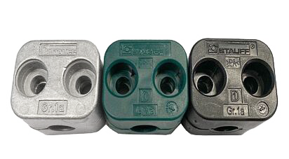
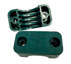
The clamp body is made of Polypropylene (PP), Polyamide (PA), Aluminium (AL), and Polypropylene with Rubber Insert (RI). These selections allow for the best performance in stabilisation and clamping of the pipes as well as temperature range system. Polypropylene material, green colour is able to work under temperatures ranging from -30˚C to +90˚C, while Polyamide, black colour works in temperatures ranging from -40˚C to +120˚C. Aluminium material, silver colour can work at a highest temperature, which is up to 300˚C. The clamps colours differently will differentiate the materials usage and lead to different temperature ranges. As for the metal component, it uses carbon steel as well as Stainless Steel SS316.
|
Material - Colour |
Body Color |
Material Code |
Temperature Range |
Polypropylene |
Green |
PP |
-30˚C to +90˚C |
Polyamide |
Black |
PA |
-40˚C to +120˚C |
Aluminium |
Silver |
AL |
Up to 300˚C |
Table 1.1: Different Clamp Body with Difference Temperature Range
Material Code |
Material Grade |
Surface Finishing |
W1 |
Carbon steel ST37.4 |
Untreated |
W2 |
Carbon steel ST37.4 |
Phosphated |
W3 |
Carbon steel ST37.4 |
Zinc/nickel plated |
W4 |
Stainless steel A2 |
1.4301/1.4305 (AISI 304/303) |
W5 |
Stainless steel A4 |
1.4401/1.4571 (AISI 316/316Ti) |
W10 |
Carbon steel ST37.4 |
Weld plate phosphated, all other parts zinc/nickel coated |
W11 |
Carbon steel ST37.4 |
Rail nut untreated, all other parts zinc/nickel coated |
Table 1.2: Material Surface Finishing of Metal Parts
3. What are the different types of clamps?
Vertical Divider
|
Standard Series PP Clamp
|
Vertical Divider
|
Heavy Series PP Clamp
|
Vertical Divider
|
Twin Series PP Clamp
|
4. How do you clamp a pipe in assembly set?
There are many ways that a pipe clamp can be put together, in order to make it most effective for its purpose. Something as simple as a base plate connected to a top plate by a hex bolt with the clamp body in the middle can be enough at times, but other more creative methods are certainly not out of the question for certain configurations. There is a possibility of using a few rail nuts in order to increase the height of the clamp, or to put two clamps on top of each other using two pairs of the clamp body and a safety locking plate.
Please look at components combination below in order to customize the installation option:
Part Numbers |
Components |
SP-PP-DP-AS |
Single weld plate, polypropylene clamp, cover plate, hexagon head bolts (x2) |
SP-PP-IS |
Single weld plate, polypropylene clamp, allan cap screws (x2) |
SPV-PP-DP-AS |
Elongated weld plate, polypropylene clamp, cover plate, hexagon head bolts (x2) |
SPV-PP-IS |
Elongated weld plate, polypropylene clamp, allan cap screws (x2) |
SM-PP-DP-AS |
Hexagon rail nut (x2), polypropylene clamp, cover plate, hexagon head bolts (x2) |
SM-PP-IS |
Hexagon rail nut (x2), polypropylene clamp, allan cap screws (x2) |
PP-DP-AS |
Polypropylene clamp, cover plate, hexagon head bolts (x2) |
PP-IS |
Polypropylene clamp, allan cap screws (x2) |
PP-SIG-AF |
Polypropylene clamp, locking plate, stacking bolt (x2) |
Table 2: Complete Set Clamp Configuration Option
5. How do you install a pipe clamp?
Stauff clamps can also be easily disassembled due to this property. Due to the fact that Stauff clamps easily configured in different manners, this means that it only requires a few creative workarounds if space is not available, and it is an option to combine different Stauff Clamps together in order to create a working system of clamps that is effective.
There are many different types of weld base plate designed according to DIN 3015 in order to install in various customizable special clamps design. Please refer to different installation methods according to job requirement:
There are many different types of weld base plate designed according to DIN 3015 in order to install in various customizable special clamps design. Please refer to different installation methods according to job requirement:
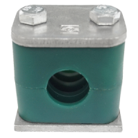
Stauff PP Clamp Body
|
Option 1: Base plate installation
Base plate installation is the most common basic application. The base plate are used to mount to the wall or ceiling and the clamps can be inserted easily before final tightening with cover plate and bolts and screws. There are two common type of threads, metric thread and unc thread to tighten the complete set of clamps. Step 1: Place base plate in the designated positions, kindly make sure the positions are suitable for system expected loads. |
Step 2: Mark the positions of the base plate to ensure the best system alignment.
Step 3: Weld the base plate into position and alternatively, elongated base plate is another option to be mounted to their positions by using two screws or bolts at both ends without any welding job.
Step 4: Push the one halves of the clamp to bottom on the base plate.
Step 5: Insert pipe, tube, cable, hose or any other type of line.
Step 6: Place the second halves of the clamp and cover plate on top and mount the complete clamp installation by using bolts and screws.
The bolts length for clamp installation refers to the installation of the base plate and mounting rails as well as stacking level during the clamp assembly. The bolts length can be customized according to job design and clamp size upon request.
Type of Thread |
Code |
Metric thread |
M |
UNC Thread |
U |
Table 3: Two Common Threaded Parts
|
Option 2: Installation on mounting rail
Mounting rails are used in installation to allow the multiple sets of clamps to be positioned along the pipe or tube. With mounting rails, the clamps can be easily adapted before final tightening and additional sets of clamps can be added or removed without any problems. Rail nuts have been made to optimize further and adapted the shape. The bottom part was lightly chamfered on both ends and the rail nuts can be screwed in further to create additional contact surface area with the mounting rail. |
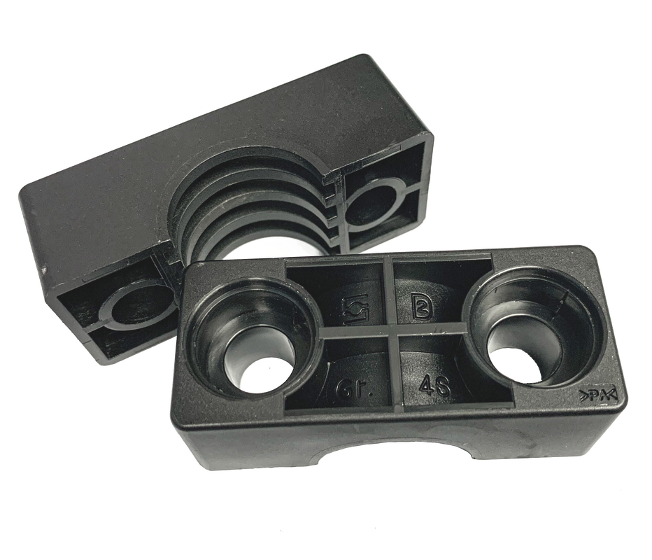
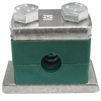
Stauff PA Clamp Body
|
The groove on the top provides a stronger attachment of the rail nuts in the mounting rail. The interaction of chamfers and grooves ensures that the rail nuts continue to remain in a temporary position even during temporary dismounting of clamps so that they will not slide out of the mounting rail as before. The conformation of the rail nut in the upper section was adapted with the plastic cap to ensure secure seating of the clamp body for vertical and overhead installation. The is no longer slides from the part and the chances of loosening will decrease as well.
Step 1: Place mounting rail in designated position and kindly ensure the expected loads is counted into consideration.
Step 2: Mark the positions of the mounting rail to ensure the best system alignment.
Step 3: Weld the mounting rails into position or it can be mounted by using side-mounting brackets with bolts or screw.
Step 4: Insert rail nuts into mounting rail and turn the position until they are locked at mounting rail for standard and twin series, while the rail nuts for heavy series has be installed through sliding in from the end of the mounting rail.
Step 5: Push one halves of the clamp body to bottom on the rail nuts.
Step 6: Insert pipe, tube, cable, hose or any other type of line.
Step 7: Place the second halves of the clamp and cover plate on top and mount the complete clamp installation by using bolts and screws.
The rail nut actual positions of the clamp assemblies can be adjusted before being firmly bolted.
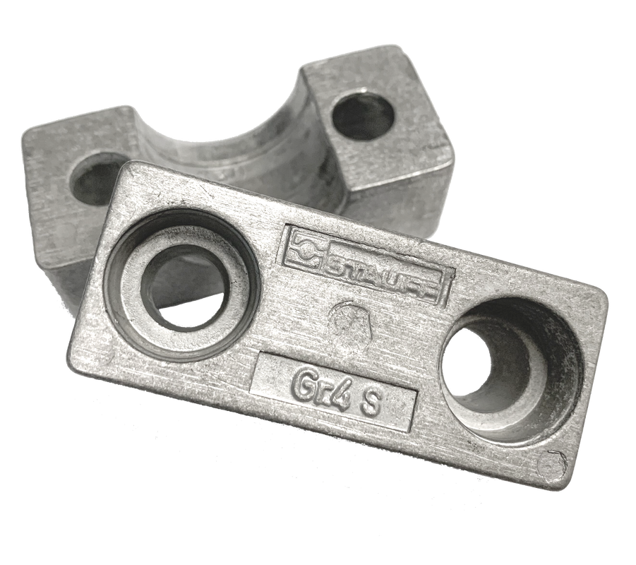
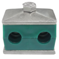
Stauff AL Clamp Body
|
Option 3: Installation of stacking clamp
The combined usage of safety locking plates and stacking bolts in clamp assembly make it possible to mount multiple clamp bodies of the identical size directly on top of one another. Installer can increase the flexibility in the design and layout of pipeline systems with the use of stacking clamps. This is because several lines running close together no longer have to be positioned side by side. Safety locking plates are insert between the levels of clamps to prevent the stacking bolts from turning around. |
Step 1: Push bottom clamp halves onto the base plate or rails nuts.
Step 2: Insert pipe, tube, cable, hose or any other type of line.
Step 3: Place the second halves of the clamp.
Step 4: Insert one piece of stacking bolt into each single bolt hole on the clamp during assembly and tighten using the tightening torques.
Step 5: Place safety locking plate on top of the first level of clamp body assembly.
Step 6: Proceed with the next levels. Insert cover plate and hexagon head bolts when reaching the top level of clamp assembly. Tighten the bolts and refer to tightening torques table.
The stacking clamps installation can be mounted both to mounting rails or base plate.
CATALOGUE :
6. What is clamp tightening torques?
The tightening torque value can be traced by torque wrench in analogue or digital formats. It is important because an under torqued bolt will deform and it is unable to provide as much clamping force as needed and an over torqued bolt will break the clamps upon installation. All bolts have to be pre-tightened by hand before applying the full tightening torque. Please refer to tightening torque values below:
The tightening torque value can be traced by torque wrench in analogue or digital formats. It is important because an under torqued bolt will deform and it is unable to provide as much clamping force as needed and an over torqued bolt will break the clamps upon installation. All bolts have to be pre-tightened by hand before applying the full tightening torque. Please refer to tightening torque values below:
Group |
Polypropylene Tightening Torque (N-m) |
Polypropylene Tightening Torque (ft-lb) |
Polyamide Tightening Torque (N-m) |
Polyamide Tightening Torque (ft-lb) |
Aluminium Tightening Torque (N-m) |
Aluminium Tightening Torque (ft-lb) |
1 |
8 |
6 |
10 |
7 |
12 |
9 |
1A |
8 |
6 |
10 |
7 |
12 |
9 |
2 |
8 |
6 |
10 |
7 |
12 |
9 |
3 |
8 |
6 |
10 |
7 |
12 |
9 |
4 |
8 |
6 |
10 |
7 |
12 |
9 |
5 |
8 |
6 |
10 |
7 |
12 |
9 |
6 |
8 |
6 |
10 |
7 |
12 |
9 |
7 |
8 |
6 |
10 |
7 |
12 |
- |
8 |
8 |
6 |
10 |
7 |
12 |
- |
Table 4.1: Tightening Torque Value for Standard Series Clamps
Group |
Polypropylene Tightening Torque (N-m) |
Polypropylene Tightening Torque (ft-lb) |
Polyamide Tightening Torque (N-m) |
Polyamide Tightening Torque (ft-lb) |
Aluminium Tightening Torque (N-m) |
Aluminium Tightening Torque (ft-lb) |
3S |
12 |
9 |
20 |
15 |
30 |
22 |
4S |
12 |
9 |
20 |
15 |
30 |
22 |
5S |
15 |
11 |
25 |
18 |
35 |
26 |
6S |
30 |
22 |
40 |
30 |
55 |
41 |
7S |
45 |
33 |
55 |
41 |
120 |
86 |
8S |
80 |
59 |
150 |
111 |
220 |
162 |
9S |
110 |
81 |
200 |
148 |
250 |
184 |
10S |
180 |
133 |
350 |
258 |
500 |
369 |
11S |
200 |
148 |
370 |
273 |
500 |
369 |
12S |
270 |
199 |
450 |
332 |
600 |
443 |
Table 4.2: Tightening Torque Value for Heavy Series Clamps
Group |
Polypropylene Tightening Torque (N-m) |
Polypropylene Tightening Torque (ft-lb) |
Polyamide Tightening Torque (N-m) |
Polyamide Tightening Torque (ft-lb) |
1D |
5 |
4 |
5 |
4 |
2D |
12 |
9 |
12 |
9 |
3D |
12 |
9 |
12 |
9 |
4D |
12 |
9 |
12 |
9 |
5D |
8 |
6 |
8 |
6 |
Table 4.3: Tightening Torque Value for Twin Series Clamps
7. What is the recommended distance between clamps?
The clamp recommended distances between clamps are important information during installation. For instance, the recommended distance to install a Stauff clamp is 1 meter away for tube outer diameter of 6 to 12.7 mm, but it can get up to as far as 7.5 meters away when the O.D of the pipe is 356 - 406 mm. The clamp lifetime can be improved if the clamp can keep in a closer distance.
The clamp recommended distances between clamps are important information during installation. For instance, the recommended distance to install a Stauff clamp is 1 meter away for tube outer diameter of 6 to 12.7 mm, but it can get up to as far as 7.5 meters away when the O.D of the pipe is 356 - 406 mm. The clamp lifetime can be improved if the clamp can keep in a closer distance.
|
Pipe bends should be supported by clamps as near to the bending curve as possible. It is recommended to design clamps in a fixed point to keep flow consistence. The first clamp should be placed directly behind the threaded coupling or connector. This is to reduce vibration for the threaded coupling or connector. If valves are incorporated in the pipelines, it is recommended that support shall be provided in front and behind of the valves.
|
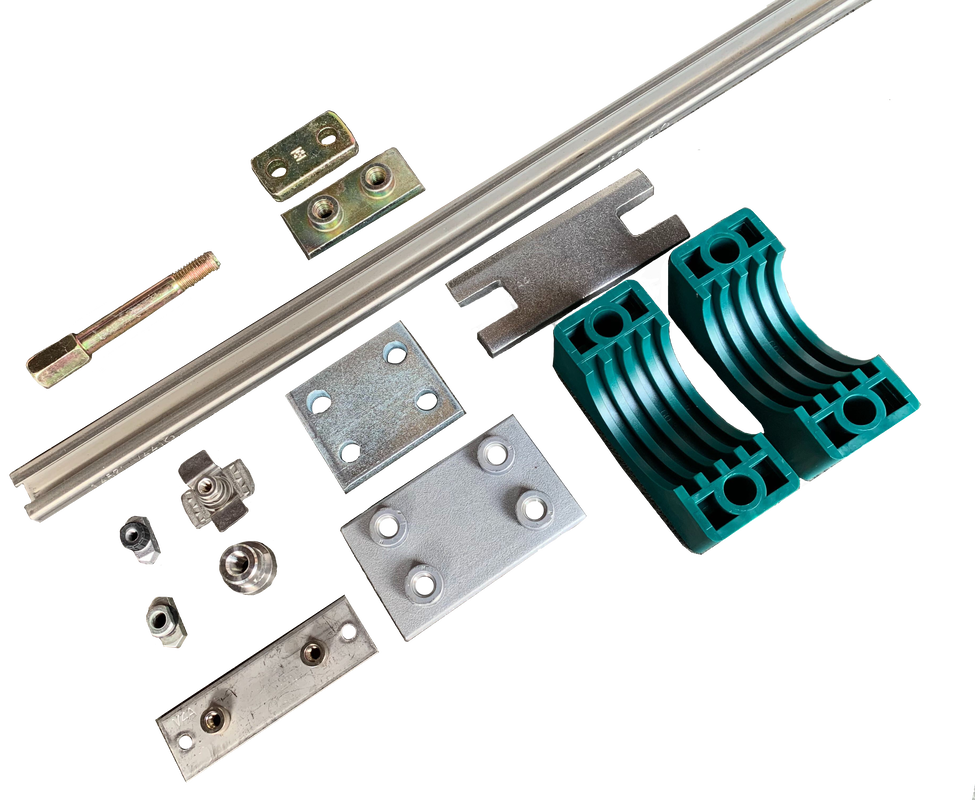
Stauff Clamp Components
|
Pipe Outer Diameter (MM) |
Distance (M) |
6.0 - 12.7 |
1.0 |
12.7 - 22.0 |
1.2 |
22.0 - 32.0 |
1.5 |
32.0 - 38.0 |
2.0 |
38.0 - 57.0 |
2.7 |
57.0 - 75.0 |
3.0 |
75.0 - 76.1 |
3.5 |
76.1 - 88.9 |
3.7 |
88.9 - 102.0 |
4.0 |
102.0 - 114.0 |
4.5 |
114.0 - 168.0 |
5.0 |
168.0 - 219.0 |
6.0 |
219.0 - 324.0 |
6.7 |
324.0 - 356.0 |
7.0 |
356.0 - 406.0 |
7.5 |
Table 5: Recommended Pipe Clamp Distance
8. What is maximum clamp load in pipeline installation?
All clamps have a maximum allowable load bearing capacity in structural supports. User has to select a clamp which is suitable for supporting the load that the system requires. The table below is a maximum load in pipe direction with an average value and is applicable for straight system installation only.
All clamps have a maximum allowable load bearing capacity in structural supports. User has to select a clamp which is suitable for supporting the load that the system requires. The table below is a maximum load in pipe direction with an average value and is applicable for straight system installation only.
Group |
Polypropylene Maximum Loads (kN) |
Polypropylene Maximum Loads (lbf) |
Polyamide Maximum Loads (kN) |
Polyamide Maximum Loads (lbf) |
Aluminium Maximum Loads (kN) |
Aluminium Maximum Loads (lbf) |
1 |
0.6 |
135 |
0.6 |
135 |
3.5 |
787 |
1A |
1.1 |
247 |
0.7 |
157 |
4.2 |
949 |
2 |
1.3 |
292 |
0.8 |
180 |
4.3 |
967 |
3 |
1.4 |
315 |
1.6 |
360 |
4.9 |
1101 |
4 |
1.5 |
337 |
1.7 |
382 |
5.0 |
1124 |
5 |
1.9 |
427 |
2.0 |
450 |
7.3 |
1641 |
6 |
2.0 |
450 |
2.5 |
562 |
8.9 |
2000 |
7 |
2.3 |
517 |
3.2 |
719 |
- |
- |
8 |
2.6 |
585 |
3.5 |
787 |
- |
- |
Table 6.1: Maximum Load in Straight Direction Pipe for Standard Series Clamps
Group |
Polypropylene Maximum Loads (kN) |
Polypropylene Maximum Loads (lbf) |
Polyamide Maximum Loads (kN) |
Polyamide Maximum Loads (lbf) |
Aluminium Maximum Loads (kN) |
Aluminium Maximum Loads (lbf) |
3S |
1.6 |
360 |
4.2 |
944 |
12.1 |
2720 |
4S |
2.9 |
652 |
4.5 |
1044 |
15.1 |
3395 |
5S |
3.3 |
742 |
5.1 |
1146 |
15.5 |
3485 |
6S |
8.2 |
1843 |
9.3 |
2090 |
29.5 |
6609 |
7S |
11.0 |
2472 |
15.8 |
3551 |
34.9 |
7845 |
8S |
14.0 |
3147 |
21.0 |
4720 |
50.0 |
11240 |
9S |
28.0 |
6300 |
32.0 |
7193 |
70.6 |
15871 |
10S |
40.0 |
8992 |
48.0 |
10790 |
84.5 |
18996 |
11S |
119.0 |
26752 |
125.0 |
27650 |
181.5 |
40802 |
12S |
168.0 |
37767 |
180.0 |
40465 |
244.5 |
54965 |
Table 6.2: Maximum load in Straight Direction Pipe for Heavy Series Clamps
Group |
Polypropylene Maximum Loads (kN) |
Polypropylene Maximum Loads (lbf) |
Polyamide Maximum Loads (kN) |
Polyamide Maximum Loads (lbf) |
1D |
0.9 |
202 |
0.9 |
202 |
2D |
2.1 |
472 |
2.2 |
495 |
3D |
1.9 |
427 |
2.0 |
450 |
4D |
2.7 |
607 |
2.9 |
652 |
5D |
1.7 |
382 |
2.5 |
562 |
Table 6.3: Maximum load in Straight Direction Pipe for Twin Series Clamps
FAQ
Are STAUFF Pipe Clamps suitable for high-pressure applications?
High-pressure applications do not impact the performance of Stauff Pipe Clamps, as they are designed for external use.
Can Pipe Clamps be used in corrosive environments?
STAUFF Pipe Clamps are available in corrosion-resistant materials such as stainless steel, making it suitable for use in harsh environments where corrosion is a concern.
Are STAUFF Pipe Clamps adjustable?
STAUFF Clamps feature adjustable design, allowing for easy installation and adaptation to different pipe diameters. Helps to accommodate variations in pipe sizes and simplifies maintenance and modifications.
Can Pipe Clamps be used for both vertical and horizontal installations?
Yes, Pipe clamps are versatile and can be used for both vertical and horizontal installations. However, it’s essential to ensure that the clamp is properly sized and installed to provide adequate support and stability.
Are there special considerations for installing STAUFF Pipe Clamps?
Yes, during installation, it is important to follow the manufacturers guidelines to ensure proper performance and longevity. This includes using the correct mounting hardware, maintaining proper spacing between clamps, and considering factors such as thermal expansion and contraction of the pipes.
CATALOGUE :
|
|
Ask a Question |