SAE Flange Check Valves
|
Check valve with SAE flange port is a spring loaded check valve type with a SAE flange adapter at both sides. The SAE flange check valve end connection is made according to ISO 6162-1 and ISO 6162-2. The check valve model type is RVZ-SAE. The SAE flange check valve is used to hydraulically lock a cylinder or other hydraulic system components by preventing return flow direction of fluids.
It is designed to interface between the components and a standard to suit with high pressure SAE flange code 61 or code 62. The main function of SAE flange check valves is to allow one flow direction and prevent any back flow in the system application. Vertical Divider
|
|
Size |
|
Material |
|
Working Pressure |
|
Connection Type |
|
CATALOGUE :
What are SAE Flange Check Valve
1. What is check valve with SAE flange ports?
Cracking pressure is the inlet pressure at which the first flow occurs. The minimum inlet pressure is required to overcome the spring or poppet tension. The spring or poppet will close the valve to prevent system back flow direction when the pressure going through the valve goes below the cracking pressure.
Free flow in one direction is allowed by a ground steel poppet valve which unseats against a 2 bar spring, which is the cracking pressure. As the flow stops, the poppet reseats to prevent return back flow thereby locking the load. Restricted back flow may be achieved by specifying an optional orifice drilled through the valve poppet. The cracking pressure can be customized upon request. Cracking pressures may deviate by -30% to +30% due to spring and manufacturing tolerances.
2. What does the arrow on a SAE flange check valve mean?
|
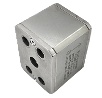
SAE flange check valve comes SAE flange adapter at both ends. There is a directional arrow marking on the check valve body to show the flow direction where the valve inlet and outlet will flow. The installation direction is critical, so that the fluids can flow into the inlet and push the poppet to allow flow out from the outlet.
The complete SAE flange check valve delivers with 1 check valve body, 2 O-rings and 2 SAE holding plates. Adapter plate is available upon request but it needs to be ordered separately. |
MHA Steel SAE Flange Check Valve
|
3. What material is a SAE flange check valve made of?
SAE Flange Check valve is usually made of carbon steel and stainless steel material. The main parts of a complete check valve include the body, poppet, seat and O-rings. Users have to ensure the valve material is suitable for their respective system application, the full material combination code is important in representing the material of different parts. Various material combination is available for customizing.
SAE Flange Check valve is usually made of carbon steel and stainless steel material. The main parts of a complete check valve include the body, poppet, seat and O-rings. Users have to ensure the valve material is suitable for their respective system application, the full material combination code is important in representing the material of different parts. Various material combination is available for customizing.
Materials |
Carbon Steel, 28p8 |
Stainless Steel, 44p8 |
Body |
Steel |
Stainless Steel |
Poppet |
Steel |
Stainless Steel |
Seat |
Polyurethane |
Polyurethane |
O-rings |
FPM |
FPM |
T min / T max |
-20°C / 100°C |
-20°C / 100°C |
Cracking Pressure |
2 Bar |
2 Bar |
4. How to order a SAE flange check valve?
SAE Flange Check valves are available from size range of 1/2” to 2” or DN15 to DN50. The valve design has a working pressure in either 210 bar and 420 bar.
SAE Flange Check valves are available from size range of 1/2” to 2” or DN15 to DN50. The valve design has a working pressure in either 210 bar and 420 bar.
DN Size |
Inches Size (") |
Type |
Working Pressure (PN) |
Unit Weight (kg) |
DN15 |
1/2" |
RVZ-DN15-SAE210 |
210 |
1.10 |
DN20 |
3/4" |
RVZ-DN20-SAE210 |
210 |
1.50 |
DN25 |
1" |
RVZ-DN25-SAE210 |
210 |
2.30 |
DN32 |
1 1/4" |
RVZ-DN32-SAE210 |
210 |
3.45 |
DN40 |
1 1/2" |
RVZ-DN40-SAE210 |
210 |
4.85 |
DN50 |
2" |
RVZ-DN50-SAE210 |
210 |
7.80 |
DN15 |
1/2" |
RVZ-DN15-SAE420 |
420 |
1.10 |
DN20 |
3/4" |
RVZ-DN20-SAE420 |
420 |
1.50 |
DN25 |
1" |
RVZ-DN25-SAE420 |
420 |
2.30 |
DN32 |
1 1/4" |
RVZ-DN32-SAE420 |
420 |
3.45 |
DN40 |
1 1/2" |
RVZ-DN40-SAE420 |
420 |
4.85 |
DN50 |
2" |
RVZ-DN50-SAE420 |
420 |
7.80 |
|
Check valve comes with SAE flange at both end connection. To apply check valve with SAE flange in system, a SAE flange female side is required to connect to both end of the flat side flange. It allows the fluid to go through the SAE flange and check valve. Hence, creating a pipeline system. There are four common SAE flange connection available. Please refer to the table below:
|
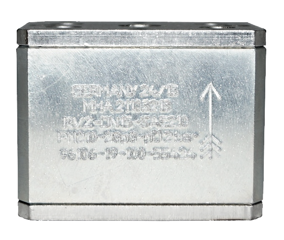
MHA SAE Flange Check Valve 210 Series
|
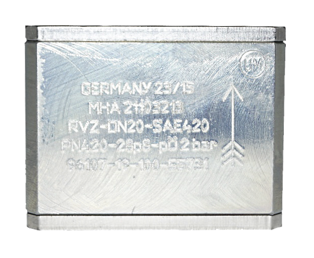
MHA SAE Flange Check Valve 420 Series
|
No |
SAE Flange End Connection |
1 |
Butt Weld (Weld on) |
2 |
Socket Weld (Weld in) |
3 |
Thread National Pipe Thread (NPT) |
4 |
Threaded British Standard Pipe Parallel (BSPP) |
5. How do you know if a SAE flange check valve is tested?
MHA-ZENTGRAF does batch test on all their valves to ensure that working pressure and leakage requirement are met before supplying them to client for installation. The batch test of ball valves is based upon DIN EN 12266-1. The standard tests are according to methods P10, P11, P12:
MHA-ZENTGRAF does batch test on all their valves to ensure that working pressure and leakage requirement are met before supplying them to client for installation. The batch test of ball valves is based upon DIN EN 12266-1. The standard tests are according to methods P10, P11, P12:
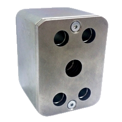
Steel SAE Flange Check Valve (6000 PSI)
|
Each heat numbers are stated in the valve testing report as identification to the final valve testing result. The testing can be done upon special request on project basis. |
CATALOGUE :