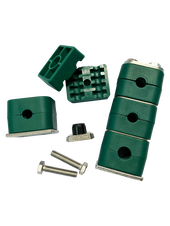
Tubeclo Tube Clamps
|
Tubeclo Tube clamp is made accordance to DIN 3015 standard and it is used to reduce the harmful effects of mechanical shock and strong vibrations in hydraulic system. Tubeclo Tube clamps are easy and quick to install and the design are fully compatible with cable trays, tubes, pipes and hoses. They are compact in design and it can be stacked and staggered to maximize the space availability.
A wide variety of tube clamp brackets are available to fit different types of industry requirement. Tubeclo Tube clamp contributes to occupational safety and environmental protection. It allows for maximum flexibility which combines single, twin and heavy clamp design. |
|
Size & Series |
|
Clamp Material and Temperature Range |
|
Accessories Material |
|
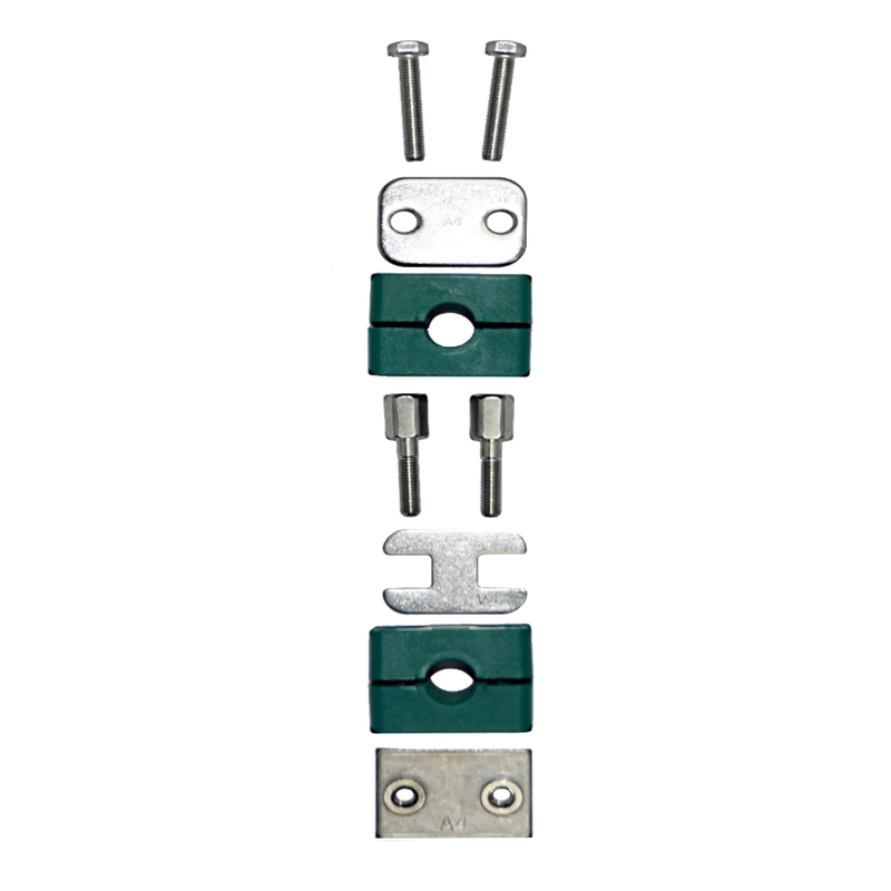
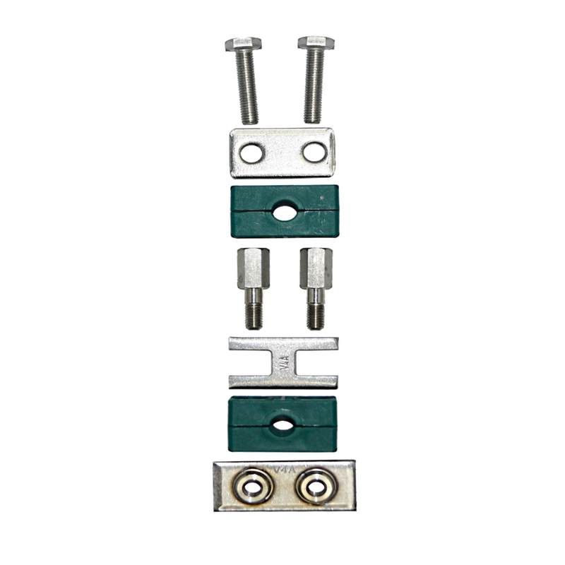
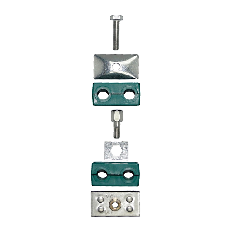
Accessories Component |
|
What are Tubeclo Tube Clamps
1. What is a Tubeclo tube clamp used for?
|
The clamp body is a square plastic design with a ribbed bore enabling secure fixing while allowing a high degree of sound deadening and tube vibration. It applies in industries such as:
|
|
|
- Vehicle Construction & Mobile Hydraulics – Construction cranes and create mixers as well as other utility vehicles, construction machines and agricultural machinery all operate with constant high pressure hydraulic system application. Tube clamp ensures that vehicle hydraulic lines are securely installed and remained firmly fixed in their original position.
2. What is the material to make of Tubeclo tube clamps?
One set of complete clamp body consists two identical clamp halves which are the top and bottom halves. Tube clamps are made of 3 common material, polypropylene, polyamide and aluminium.
Material Code |
Material |
Design |
Colour |
PP |
Polypropylene |
Profile inside, With tension clearance |
Green |
PA |
Polyamide |
Profile inside, With tension clearance |
Black |
PPH |
Polypropylene |
Smooth inside, Without tension clearance |
Green |
PAH |
Polyamide |
Smooth inside, Without tension clearance |
Black |
ALU |
Aluminium |
Profile inside, With tension clearance |
Aluminium |
Table 1: Clamp Body Design and Colour
While the accessories material and surface finishing are available in steel and stainless steel material.
Material Grade |
Surface coating |
Code |
Carbon Steel ST37 |
Untreated |
W1 |
Carbon Steel ST37 |
Phosphated |
W2 |
Carbon Steel ST37 |
Zinc/nickel coated |
W3 |
Stainless Steel A2 |
1.4301/1.4305 (AISI 304/303) |
W4 |
Stainless Steel A4 |
1.4401/1.4571 (AISIS 316/316Ti) |
W5 |
Table 2: Accessories Material Code
3. How do you use a Tubeclo tube clamp?
There are available in standard, heavy and twin series. It is recommended for the safe installation of rigid pipes, tubes or hoses. Tubes clamp can be assembled according to customer or project specifications. Each accessories component have their own order code.
There are available in standard, heavy and twin series. It is recommended for the safe installation of rigid pipes, tubes or hoses. Tubes clamp can be assembled according to customer or project specifications. Each accessories component have their own order code.
Component Code |
Component Name |
Group Size |
SP |
Single Weld Plate |
SP1 - SP8 |
SPV |
Elongated Weld Plate |
SPV1 - SPV8 |
CRA |
Channel Rail Adaptor |
CRA1 - 8 |
RAP |
Group Weld Plate |
RAP1/30/10 – RAP6/90/5 |
DP |
Cover Plate |
DP1 – DP8 |
AS |
Hexagon Head Bolt |
AS1M – AS8M |
IS |
Socket Cap Screw |
IS1M – IS8M |
AF |
Stacking Bolt |
AF1 – AF8 |
SIG |
Safety Locking Plate |
SIG1 – SIG8 |
TS |
Mounting Rail |
TS11,TS14, TS30 |
SM |
Hexagon Rail Nut |
SM1-8/1D |
Table 3: Standard Series Component Name and Code
Component Code |
Component Name |
Group Size |
SPAL |
Weld Plate for Single Clamps |
SPAL3S – SPAL12S |
SPAS |
Weld Plate for Double Clamps |
SPAS3S – SPAS12S |
CRA |
Channel Rail Adaptor |
CRA3SM – CRA6 M |
SPAL/DUEB |
Elongated Weld Plate for Single Clamps |
SPAL/DUEB3S – SPAL/DUEB12S |
DPAL |
Cover Plate for Single Clamps |
DPAL3S – DPAL12S |
DPAS |
Cover Plate for Double Clamps |
DPAS3S – DPAS12S |
AS |
Hexagon Head Bolt |
AS3SM – AS12SM |
IS |
Socket Cap Screw |
IS3SM – IS6SM |
AF |
Stacking Bolt |
AF3S – AF10S |
SIP |
Safety Locking Plate |
SIP3S – SIP10S |
STSV |
Mounting Rail |
STSV |
GMV |
Mounting Rail Nut |
GMV3 – 6S |
Table 4: Heavy Series Component Name and Code
Component Code |
Component Name |
Group Size |
SP |
Single Weld Plate |
SP1D – SP5D |
RAP |
Group Weld Plate |
RAP1D/40/5 – RAP5D/112/5 |
CRA |
Channel Rail Adaptor |
CRA1DM – CRA5DM |
GD |
Cover Plate |
GD1D – GD5D |
AS |
Hexagon Head Bolt |
AS1DM – AS5DM |
AF |
Stacking Bolt |
AF1D – AF5D |
SIV |
Safety Locking Plate |
SIV1D – SIV3D |
TS |
Mounting Rail |
TS11,TS14, TS30 |
SM |
Hexagon Rail Nut |
SM1-8/1D, SM2-5D |
Table 5: Twin Series Component Name and Code
There are alternative ways for clamps assembly according to project requirement.
Here are some basic installation instructions:
Here are some basic installation instructions:
- Installation with bottom base plate
Step 2: Adjust the position of bottom base plates to ensure correct alignment.
Step 3: Weld the bottom base plate into position. Alternatively, elongated bottom base plate can also be mounted to their positions by using hex bolt or Allan cap screw.
Step 3: Push bottom half halve clamp onto bottom base plate.
Step 4: Insert tube, hose or cable and then place second half halve clamp and cover plate on top. Mount clamp assembly by using hex bolt and Allan cap screw.
Step 2: Adjust the position of mounting rail to ensure best alignment. Step 3: Weld mounting rails into position. Mounting rails can be mounted to their positions by using side-mounting brackets with hex bolt and Allan cap screw. |
Step 4: Insert mounting rail nuts into mounting rail and turn until stop to lock for standard or twin series or slide in rail nuts for heavy series.
Step 5: Push bottom half halve clamp body onto rail nuts.
Step 6: Insert tube, hose or cable and then place another half halve clamp and cover plate on top. Mount clamp assembly by using hex bolt and Allan cap screw.
Step 5: Push bottom half halve clamp body onto rail nuts.
Step 6: Insert tube, hose or cable and then place another half halve clamp and cover plate on top. Mount clamp assembly by using hex bolt and Allan cap screw.
Step 2: Insert tube, hose or cable and place second half halve clamp on top. Step 3: Insert stacking bolts into the clamp assembly and tighten using the recommended tightening torques Step 4: Place safety locking plate on top before clamp assembly. Proceed with next levels. Top level to be assembled with cover top plate and hexagon head bolts. |
4. How much weight can a Tubeclo tube clamp hold?
The tube clamp has maximum allowable load capacity in holding tubes, pipes, hoses or other structural. Installer has to decide the tube size and clamp design that system requires.
The tube clamp has maximum allowable load capacity in holding tubes, pipes, hoses or other structural. Installer has to decide the tube size and clamp design that system requires.
Group |
Hexagon Head Bolt |
Polypropylene Maximum Loads (kN) |
Polypropylene Maximum Loads (lbf) |
Polyamide Maximum Loads (kN) |
Polyamide Maximum Loads (lbf) |
Aluminium Maximum Loads (kN) |
Aluminium Maximum Loads (lbf) |
1 |
M6 or 1/4-20 UNC |
0.6 |
135 |
0.6 |
135 |
3.5 |
787 |
1A |
M6 or 1/4-20 UNC |
1.1 |
247 |
0.7 |
157 |
4.2 |
949 |
2 |
M6 or 1/4-20 UNC |
1.3 |
292 |
0.8 |
180 |
4.3 |
967 |
3 |
M6 or 1/4-20 UNC |
1.4 |
315 |
1.6 |
360 |
4.9 |
1101 |
4 |
M6 or 1/4-20 UNC |
1.5 |
337 |
1.7 |
382 |
5.0 |
1124 |
5 |
M6 or 1/4-20 UNC |
1.9 |
427 |
2.0 |
450 |
7.3 |
1641 |
6 |
M6 or 1/4-20 UNC |
2.0 |
450 |
2.5 |
562 |
8.9 |
2000 |
7 |
M6 or 1/4-20 UNC |
2.3 |
517 |
3.2 |
719 |
- |
- |
8 |
M6 or 1/4-20 UNC |
2.6 |
585 |
3.5 |
787 |
- |
- |
Table 6: Maximum Load in Straight Direction Pipe for Standard Series Clamps
Group |
Hexagon Head Bolt |
Polypropylene Maximum Loads (kN) |
Polypropylene Maximum Loads (lbf) |
Polyamide Maximum Loads (kN) |
Polyamide Maximum Loads (lbf) |
Aluminium Maximum Loads (kN) |
Aluminium Maximum Loads (lbf) |
3S |
M10 or 3/8-16 UNC |
1.6 |
360 |
4.2 |
944 |
12.1 |
2720 |
4S |
M10 or 3/8-16 UNC |
2.9 |
652 |
4.5 |
1044 |
15.1 |
3395 |
5S |
M10 or 3/8-16 UNC |
3.3 |
742 |
5.1 |
1146 |
15.5 |
3485 |
6S |
M12 or 7/16-14 UNC |
8.2 |
1843 |
9.3 |
2090 |
29.5 |
6609 |
7S |
M16 or 5/8-11 UNC |
11.0 |
2472 |
15.8 |
3551 |
34.9 |
7805 |
8S |
M20 or 3/4-10 UNC |
14.0 |
3147 |
21.0 |
4772 |
50.0 |
11240 |
9S |
M24 or 7/8-9 UNC |
28.0 |
6300 |
32.0 |
7193 |
70.6 |
15871 |
10S |
M30 or 1 1/8-7 UNC |
40.0 |
8992 |
48.0 |
10790 |
84.5 |
18996 |
11S |
M30 or 1 1/4-7 UNC |
119.0 |
26752 |
125.0 |
27650 |
181.5 |
40802 |
12S |
M30 or 1 1/4-7 UNC |
168.0 |
37767 |
180.0 |
40465 |
244.5 |
54965 |
Table 7: Maximum Load in Straight Direction Pipe for Heavy Series Clamps
Group |
Hexagon Head Bolt |
Polypropylene Maximum Loads (kN) |
Polypropylene Maximum Loads (lbf) |
Polyamide Maximum Loads (kN) |
Polyamide Maximum Loads (lbf) |
1D |
M6 or 1/4-20 UNC |
0.9 |
202 |
0.9 |
202 |
2D |
M8 or 5/16-18 UNC |
2.1 |
472 |
2.2 |
495 |
3D |
M8 or 5/16-18 UNC |
1.9 |
427 |
2.0 |
450 |
4D |
M8 or 5/16-18 UNC |
2.7 |
607 |
2.9 |
652 |
5D |
M8 or 5/16-18 UNC |
1.7 |
382 |
2.5 |
562 |
Table 8: Maximum Load in Straight Direction Pipe for Twin Series Clamps

