Hydraulics Steel Tubes
Hydraulic tube is made according to DIN 2391/C (DIN EN 10305-1) or DIN 2445/2 (DIN EN 10305-4) standards and it is available in millimeters, inches outer diameter, and inches nominal bore size.
Size |
|
Material Specifications |
|
Dimension Specifications |
|
Finishing |
|
What are Hydraulics Steel Tube Specification
EN 10305-4 Hydraulic Steel Tubes
|
The hydraulic tube is cylinder-like shaped tubing device that when attach to hydraulic systems, allow for the passage of fluids within and among components. The tube standard specifies dimensions for cold drawn finishing and seamless precision steel tubes. Cold drawn process provides the tube with close dimensional tolerances, increase material strength and enhanced machinability. Therefore, hydraulics steel tubes are suitable in high performance piping system application.
|
|
There are two type of material grade, ST52.4 and ST37.4. ST52.4 is high tensile strength tube means it has higher permissible working pressures by reduced tube wall thickness, and leading to reduced system overall weight. Please refer to chemical composition for ST52.4 and ST37.4 tube material:
|
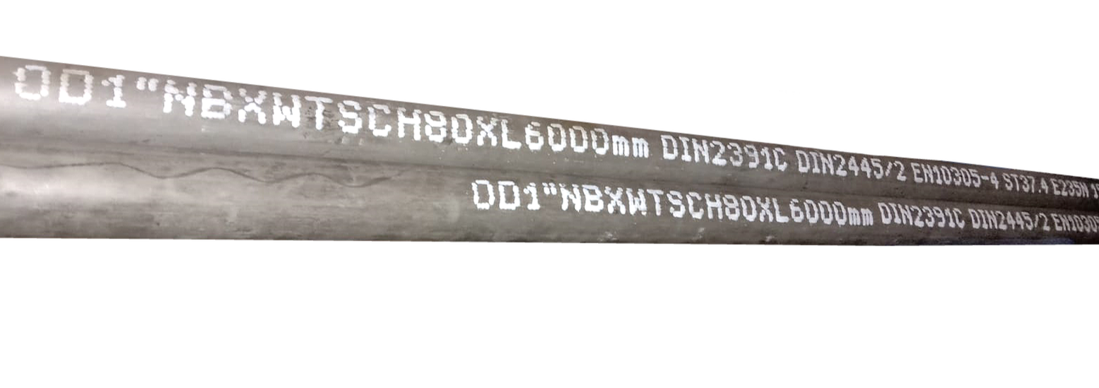
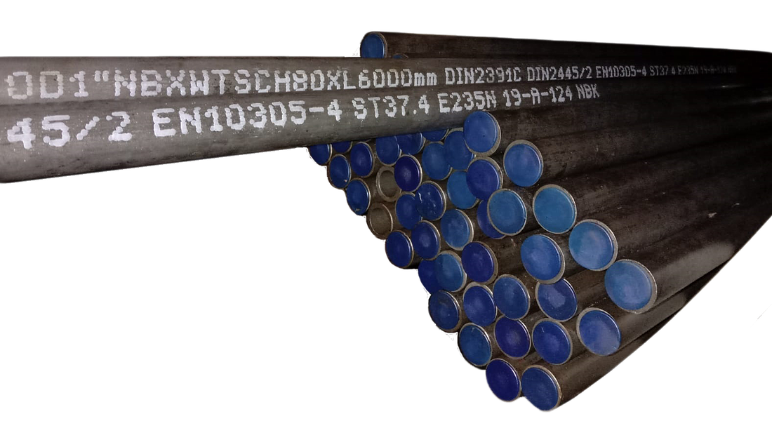
1" Nominal Bore x Schedule 80 Hydraulic Steel Tubes
|
Chemical Composition (%) |
Carbon (C) |
Silicon (Si) |
Manganese (Mn) |
Phosphorus (P) |
Sulfur (S) |
E355 (ST52.4) |
⩽ 0.22 |
⩽ 0.55 |
⩽ 1.6 |
⩽ 0.045 |
⩽ 0.045 |
E235 (ST37.4) |
⩽ 0.17 |
⩽ 0.35 |
⩽ 1.2 |
⩽ 0.045 |
⩽ 0.045 |
When choosing between these two grades, it's important to consider the specific requirements of the application. ST37.4 might be preferred for applications where ductility and weldability are critical, while ST52.4 could be chosen for applications where higher strength and hardness are needed, even if it means sacrificing some ductility.
Tensile strength ranges for ST52.4 from 490 N/mm² to 630 N/mm², while the ranges for ST37.4 are from 340 N/mm² to 480 N/mm². Different steel grades lead to different yield strengths too. The minimum yield strength for ST52.4 is 355 MPa and while for ST37.4 is 235 MPa. However, if the steel tubes with a thickness that is smaller than 3.0MM and an outside diameter that is smaller than 30MM and, the minimum yield strength is 10 MPa lower
Hydraulic Steel Tubes
|
The finishing of tubes surface under ST37.4 and ST52.4 material are NBK, where the tubes are phosphate and normalized which provides corrosion resistance. It is oiled inside and outside. Normalize process creates tougher metal products. In the normalizing process, metals are heated to high temperatures and then allowed to naturally cool back down to room temperature by exposure after heating. Through the process, the metals are likely to be more formable, harder and ductile.
|
The choice between hot-dipped and cold-dipped galvanizing for hydraulic steel tubes depends on factors such as the intended application, environmental conditions, and desired level of corrosion protection. Both methods play a crucial role in extending the lifespan and performance of hydraulic systems in various industrial and commercial settings.
Hot Dipped Galvanizing:
- Process - Involves immersing the steel tubes into a bath of molten zinc at a high temperature. The zinc reacts with the steel to form a metallurgical bond, creating a thick, durable coating.
- Coating Thickness - Thicker and more robust compared to cold-dipped coatings. Provides a superior corrosion protection, making it ideal for harsh environments.
- Application - Often preferred for large-scale production runs and applications where maximum corrosion resistance is required, such as outdoor structures, marine environments, and industrial equipment.
Cold Dipped Galvanizing:
- Process - Also known as electro-galvanizing, involves applying a thin layer of zinc onto the steel surface through an electrolytic process. Steel tubes are submerged in an electrolyte solution containing zinc ions, electric current is passed through the solution to deposit the zinc coating on the steel.
- Coating Thickness - Thinner and more uniform compared to hot-dipped coatings. White not as corrosion-resistant as hot-dipped coatings, they still provide effective protection against rust and corrosion in less aggressive environments.
- Applications - Often used for smaller-scale production runs, intricate parts, and applications where a thinner coating is sufficient, such as indoor structures, automotive components, and electrical enclosures.
There are two options of tube production, seamless or welded. Our hydraulics steel tubes are made from seamless process and it comes without a weld-join or a seam as it is drawn form a billet.
Allowable working pressures are calculated using as per DIN 2413 at normal temperature. The yield and tensile stress values utilize to determine the maximum allowable running pressure and wall thickness required. The tubes and pipes are delivered the actual yield and tensile stress values are verified from the true copy material certificates. Pressure reduction factors at various temperatures show below:
° C |
-40 |
120 |
150 |
175 |
200 |
250 |
° F |
-40 |
248 |
302 |
347 |
392 |
482 |
Rating Factor |
0.90 |
1.0 |
0.89 |
0.89 |
0.83 |
NA |
- Hydraulic Machinery
- Aerospace and aviation
- Oil and Gas Sector
- Marine Industry
|
Hydraulic tubes are suitable for welding according to usual techniques. A bending radius of 3x the external tube outer diameter is recommended for cold bending of tubes with instrument tube bender or manual hand bending. Welding Filler should be selected in accordance to DIN EN 1600 and DIN EN 12072 part 1 taking into account of the welding skill sets and type of application.
Here is the 4 simple steps process of hydraulics steel tube installation guidelines: |
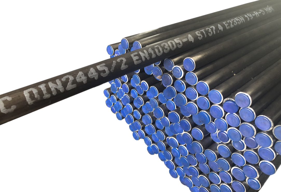
DIN 2445/2 (ST37.4) Hydraulic Steel Tubes
|
Step 2: Bend the tube - This is mostly done using hydraulic tube bender or manually bending.
Step 3: Welding - To weld, you go through three processes, the weld bevel process, choosing the appropriate welding methods and lastly carefully check your handiwork after welding.
Step 4: Installation - This is done when both the hydraulic component and connected equipment has been installed. After clarifying the sequence and become familiar with the pipe scheme, using a pipe clamp, you can reduce the tube vibration when flow went through.
|
Description |
Working Pressure (Bar) |
Burst Pressure (Bar) |
IMPA CODE |
|
|
1 |
4MM OD x 1.0MM THK x 6 MTR |
707 |
1755 |
710701 |
|
2 |
5MM OD x 1.0MM THK x 6 MTR |
565 |
1404 |
- |
|
3 |
6MM OD x 1.0MM THK x 6 MTR |
471 |
1170 |
710702 |
|
4 |
6MM OD x 1.5MM THK x 6 MTR |
707 |
1755 |
710703 |
|
5 |
8MM OD x 1.0MM THK x 6 MTR |
353 |
878 |
710704 |
|
6 |
8MM OD x 1.5MM THK x 6 MTR |
530 |
1316 |
710705 |
|
7 |
8MM OD x 2.0MM THK x 6 MTR |
707 |
1755 |
710706 |
|
8 |
8MM OD x 2.5MM THK x 6 MTR |
883 |
2194 |
- |
|
9 |
10MM OD x 1.0MM THK x 6 MTR |
283 |
702 |
710707 |
|
10 |
10MM OD x 1.2MM THK x 6 MTR |
339 |
845 |
710708 |
|
11 |
10MM OD x 1.5MM THK x 6 MTR |
424 |
1053 |
710709 |
|
12 |
10MM OD x 2.0MM THK x 6 MTR |
565 |
1404 |
710710 |
|
13 |
10MM OD x 2.5MM THK x 6 MTR |
707 |
1755 |
- |
|
14 |
12MM OD x 1.0MM THK x 6 MTR |
236 |
585 |
710711 |
|
15 |
12MM OD x 1.2MM THK x 6 MTR |
283 |
702 |
710712 |
|
16 |
12MM OD x 1.5MM THK x 6 MTR |
353 |
878 |
710713 |
|
17 |
12MM OD x 2.0MM THK x 6 MTR |
471 |
1170 |
710714 |
|
18 |
12MM OD x 2.5MM THK x 6 MTR |
589 |
1463 |
- |
|
19 |
12MM OD x 3.0MM THK x 6 MTR |
707 |
1755 |
- |
|
20 |
14MM OD x 1.5MM THK x 6 MTR |
303 |
752 |
- |
|
21 |
14MM OD x 2.0MM THK x 6 MTR |
404 |
1003 |
- |
|
22 |
14MM OD x 2.5MM THK x 6 MTR |
505 |
1254 |
- |
|
23 |
14MM OD x 3.0MM THK x 6 MTR |
606 |
1504 |
- |
|
24 |
14MM OD x 4.0MM THK x 6 MTR |
807 |
2006 |
- |
|
25 |
15MM OD x 1.0MM THK x 6 MTR |
188 |
468 |
- |
|
26 |
15MM OD x 1.2MM THK x 6 MTR |
226 |
562 |
710715 |
|
27 |
15MM OD x 1.5MM THK x 6 MTR |
283 |
702 |
710716 |
|
28 |
15MM OD x 2.0MM THK x 6 MTR |
377 |
936 |
710717 |
|
29 |
15MM OD x 2.5MM THK x 6 MTR |
471 |
1170 |
710718 |
|
30 |
15MM OD x 3.0MM THK x 6 MTR |
565 |
1404 |
- |
|
31 |
16MM OD x 1.5MM THK x 6 MTR |
265 |
658 |
710719 |
|
32 |
16MM OD x 2.0MM THK x 6 MTR |
353 |
878 |
710720 |
|
33 |
16MM OD x 3.0MM THK x 6 MTR |
530 |
1316 |
- |
|
34 |
18MM OD x 1.5MM THK x 6 MTR |
236 |
585 |
710721 |
|
35 |
18MM OD x 2.0MM THK x 6 MTR |
314 |
780 |
710722 |
|
36 |
18MM OD x 2.5MM THK x 6 MTR |
393 |
975 |
710723 |
|
37 |
18MM OD x 3.0MM THK x 6 MTR |
471 |
1170 |
- |
|
38 |
20MM OD x 2.0MM THK x 6 MTR |
283 |
702 |
710724 |
|
39 |
20MM OD x 2.5MM THK x 6 MTR |
353 |
878 |
710725 |
|
40 |
20MM OD x 3.0MM THK x 6 MTR |
424 |
1053 |
710726 |
|
41 |
20MM OD x 3.5MM THK x 6 MTR |
495 |
1229 |
- |
|
42 |
20MM OD x 4.0MM THK x 6 MTR |
565 |
1404 |
- |
|
Description |
Working Pressure (Bar) |
Burst Pressure (Bar) |
IMPA CODE |
|
|
43 |
20MM OD x 4.5MM THK x 6 MTR |
636 |
1580 |
- |
|
44 |
20MM OD x 5.0MM THK x 6 MTR |
707 |
1755 |
- |
|
45 |
22MM OD x 2.0MM THK x 6 MTR |
257 |
638 |
710727 |
|
46 |
22MM OD x 2.5MM THK x 6 MTR |
321 |
798 |
- |
|
47 |
22MM OD x 3.0MM THK x 6 MTR |
385 |
957 |
710728 |
|
48 |
22MM OD x 4.0MM THK x 6 MTR |
514 |
1276 |
- |
|
49 |
25MM OD x 2.0MM THK x 6 MTR |
226 |
562 |
710729 |
|
50 |
25MM OD x 2.5MM THK x 6 MTR |
283 |
702 |
710730 |
|
51 |
25MM OD x 3.0MM THK x 6 MTR |
339 |
842 |
710731 |
|
52 |
25MM OD x 3.5MM THK x 6 MTR |
396 |
983 |
- |
|
53 |
25MM OD x 4.0MM THK x 6 MTR |
452 |
1123 |
- |
|
54 |
25MM OD x 5.0MM THK x 6 MTR |
565 |
1404 |
- |
|
55 |
28MM OD x 2.0MM THK x 6 MTR |
202 |
501 |
- |
|
56 |
28MM OD x 2.5MM THK x 6 MTR |
252 |
627 |
710732 |
|
57 |
28MM OD x 3.0MM THK x 6 MTR |
303 |
752 |
- |
|
58 |
28MM OD x 4.0MM THK x 3 MTR |
404 |
1003 |
- |
|
59 |
28MM OD x 5.0MM THK x 6 MTR |
505 |
1254 |
- |
|
60 |
30MM OD x 2.0MM THK x 6 MTR |
188 |
468 |
- |
|
61 |
30MM OD x 2.5MM THK x 6 MTR |
236 |
585 |
710733 |
|
62 |
30MM OD x 3.0MM THK x 6 MTR |
283 |
702 |
- |
|
63 |
30MM OD x 4.0MM THK x 6 MTR |
377 |
936 |
- |
|
64 |
30MM OD x 5.0MM THK x 6 MTR |
471 |
1170 |
- |
|
65 |
35MM OD x 2.0MM THK x 6 MTR |
161 |
401 |
- |
|
66 |
35MM OD x 2.5MM THK x 6 MTR |
202 |
501 |
710734 |
|
67 |
35MM OD x 3.0MM THK x 6 MTR |
242 |
602 |
- |
|
68 |
35MM OD x 4.0MM THK x 6 MTR |
323 |
802 |
710735 |
|
69 |
35MM OD x 5.0MM THK x 6 MTR |
404 |
1003 |
- |
|
70 |
38MM OD x 3.0MM THK x 6 MTR |
223 |
554 |
- |
|
71 |
38MM OD x 4.0MM THK x 6 MTR |
297 |
739 |
- |
|
72 |
38MM OD x 5.0MM THK x 6 MTR |
372 |
924 |
- |
|
73 |
42MM OD x 2.0MM THK x 6 MTR |
135 |
334 |
- |
|
74 |
42MM OD x 3.0MM THK x 6 MTR |
202 |
501 |
- |
|
75 |
42MM OD x 4.0MM THK x 6 MTR |
269 |
669 |
710736 |
|
76 |
42MM OD x 5.0MM THK x 6 MTR |
336 |
836 |
- |
|
77 |
50MM OD x 3.0MM THK x 6 MTR |
170 |
421 |
- |
|
78 |
50MM OD x 5.0MM THK x 6 MTR |
283 |
702 |
- |
|
79 |
60MM OD x 3.0MM THK x 6 MTR |
141 |
351 |
- |
|
80 |
60MM OD x 5.0MM THK x 6 MTR |
236 |
585 |
- |
|
81 |
65MM OD x 6.0MM THK x 6 MTR |
261 |
648 |
- |
|
82 |
75MM OD x 3.0MM THK x 6 MTR |
113 |
281 |
- |
|
83 |
1/8"NB x 2.41MM THK x 6 MTR |
649 |
1611 |
- |
|
84 |
1/4"NB x 3.02MM THK x 6 MTR |
618 |
1536 |
- |
|
Description |
Working Pressure (Bar) |
Burst Pressure (Bar) |
IMPA CODE |
|
|
85 |
3/8"NB x 3.2MM THK x 6 MTR |
523 |
1298 |
- |
|
86 |
1/2"NB x 3.0MM THK x 6 MTR |
391 |
971 |
- |
|
87 |
3/4"NB x 3.0MM THK x 6 MTR |
312 |
774 |
- |
|
88 |
1"NB x 3.5MM THK x 6 MTR |
291 |
723 |
- |
|
89 |
1"NB x 4.55MM THK x 6 MTR |
378 |
939 |
- |
|
90 |
1 1/4"NB x 4.85MM THK x 6 MTR |
321 |
797 |
- |
|
91 |
1 1/2"NB x 5.08MM THK x 6 MTR |
295 |
734 |
- |
|
92 |
2 1/2"NB x 6.3MM THK x 6 MTR |
NIL |
580 |
- |
|
93 |
1/4"OD x 1.2MM THK x 6 MTR |
534 |
1327 |
- |
|
94 |
1/4"OD x 1.5MM THK x 6 MTR |
668 |
1658 |
- |
|
95 |
3/8"OD x 1.22MM THK x 6 MTR |
362 |
899 |
- |
|
96 |
3/8"OD x 1.5MM THK x 6 MTR |
445 |
1105 |
- |
|
97 |
1/2"OD x 1.5MM THK x 6 MTR |
334 |
829 |
- |
|
98 |
3/4"OD x 2.0MM THK x 6 MTR |
297 |
737 |
- |
|
99 |
3/4"OD x 2.64MM THK x 6 MTR |
392 |
973 |
- |
|
100 |
1"OD x 3.0MM THK x 6 MTR |
334 |
829 |
- |
|
101 |
1 1/4"OD x 3.0MM THK x 6 MTR |
267 |
663 |
- |
|
102 |
1 1/4"OD x 3.25MM THK x 6 MTR |
289 |
719 |
- |
|
Description |
Working Pressure (Bar) |
Burst Pressure (Bar) |
IMPA CODE |
|
|
103 |
10MM OD x 2.0MM THK x 6 MTR |
799 |
1919 |
710710 |
|
104 |
12MM OD x 2.0MM THK x 6 MTR |
666 |
1599 |
710714 |
|
105 |
14MM OD x 1.5MM THK x 6 MTR |
428 |
1028 |
- |
|
106 |
14MM OD x 2.0MM THK x 6 MTR |
571 |
1371 |
- |
|
107 |
15MM OD x 1.5MM THK x 6 MTR |
400 |
959 |
710716 |
|
108 |
15MM OD x 2.0MM THK x 6 MTR |
533 |
1279 |
710717 |
|
109 |
15MM OD x 2.5MM THK x 6 MTR |
666 |
1599 |
710718 |
|
110 |
16MM OD x 1.5MM THK x 6 MTR |
375 |
899 |
710719 |
|
111 |
16MM OD x 2.0MM THK x 6 MTR |
500 |
1199 |
710720 |
|
112 |
16MM OD x 3.0MM THK x 6 MTR |
749 |
1799 |
- |
|
113 |
18MM OD x 1.5MM THK x 6 MTR |
333 |
800 |
710721 |
|
114 |
18MM OD x 2.0MM THK x 6 MTR |
444 |
1066 |
710722 |
|
115 |
20MM OD x 2.0MM THK x 6 MTR |
400 |
959 |
710724 |
|
116 |
20MM OD x 2.5MM THK x 6 MTR |
500 |
1199 |
710725 |
|
117 |
20MM OD x 3.0MM THK x 6 MTR |
599 |
1439 |
710726 |
|
118 |
22MM OD x 2.0MM THK x 6 MTR |
363 |
872 |
710727 |
|
119 |
25MM OD x 2.0MM THK x 6 MTR |
320 |
768 |
710729 |
|
120 |
25MM OD x 2.5MM THK x 6 MTR |
400 |
959 |
710730 |
|
121 |
25MM OD x 3.0MM THK x 6 MTR |
480 |
1151 |
710731 |
|
122 |
25MM OD x 4.0MM THK x 6 MTR |
639 |
1535 |
- |
|
123 |
25MM OD x 5.0MM THK x 6 MTR |
799 |
1919 |
- |
|
124 |
28MM OD x 2.0MM THK x 6 MTR |
285 |
685 |
- |
|
125 |
28MM OD x 3.0MM THK x 6 MTR |
428 |
1028 |
- |
|
126 |
30MM OD x 2.0MM THK x 6 MTR |
266 |
640 |
- |
|
127 |
30MM OD x 3.0MM THK x 6 MTR |
400 |
959 |
- |
|
128 |
30MM OD x 4.0MM THK x 6 MTR |
533 |
1279 |
- |
|
129 |
35MM OD x 3.0MM THK x 6 MTR |
343 |
822 |
- |
|
130 |
35MM OD x 4.0MM THK x 6 MTR |
457 |
1096 |
710735 |
|
131 |
38MM OD x 3.0MM THK x 6 MTR |
315 |
757 |
- |
|
132 |
38MM OD x 4.0MM THK x 6 MTR |
421 |
1010 |
- |
|
133 |
38MM OD x 5.0MM THK x 6 MTR |
526 |
1262 |
- |
|
134 |
42MM OD x 3.0MM THK x 6 MTR |
285 |
685 |
- |
|
135 |
42MM OD x 4.0MM THK x 6 MTR |
381 |
914 |
710736 |
|
136 |
42MM OD x 5.0MM THK x 6 MTR |
476 |
1142 |
- |
|
137 |
45MM OD x 5.0MM THK x 6 MTR |
444 |
1066 |
- |
|
138 |
50MM OD x 5.0MM THK x 6 MTR |
400 |
959 |
- |
|
139 |
50MM OD x 6.0MM THK x 6 MTR |
480 |
1151 |
- |
|
140 |
50MM OD x 10.0MM THK x 6 MTR |
799 |
1919 |
- |
|
141 |
54MM OD x 6.0MM THK x 6 MTR |
444 |
1066 |
- |
|
142 |
60MM OD x 5.0MM THK x 6 MTR |
333 |
800 |
- |
|
143 |
60MM OD x 6.0MM THK x 6 MTR |
400 |
959 |
- |
|
Description |
Working Pressure (Bar) |
Burst Pressure (Bar) |
IMPA CODE |
|
|
144 |
65MM OD x 8.0MM THK x 6 MTR |
492 |
1181 |
- |
|
145 |
66MM OD x 8.5MM THK x 6 MTR |
515 |
1236 |
- |
|
146 |
76.1MM OD x 6.3MM THK x 6 MTR |
331 |
794 |
- |
|
147 |
80MM OD x 10.0MM THK x 6 MTR |
500 |
1199 |
- |
|
148 |
90MM OD x 5.0MM THK x 6 MTR |
222 |
533 |
- |
|
149 |
90MM OD x 10.0MM THK x 6 MTR |
444 |
1066 |
- |
|
150 |
97MM OD x 12.0MM THK x 6 MTR |
494 |
1187 |
- |
|
151 |
100MM OD x 10.0MM THK x 6 MTR |
400 |
959 |
- |
|
152 |
115MM OD x 15.0MM THK x 6 MTR |
521 |
1251 |
- |
|
153 |
120MM OD x 12.0MM THK x 6 MTR |
400 |
959 |
- |
|
154 |
130MM OD x 15.0MM THK x 6 MTR |
461 |
1107 |
- |
|
155 |
150MM OD x 15.0MM THK x 6 MTR |
400 |
959 |
- |
|
156 |
190MM OD x 20.0MM THK x 6 MTR |
421 |
1010 |
- |
|
157 |
2"OD x 5.9MM THK x 6 MTR |
464 |
1114 |
- |
|
158 |
2"OD x 6.0MM THK x 6 MTR |
472 |
1133 |
- |